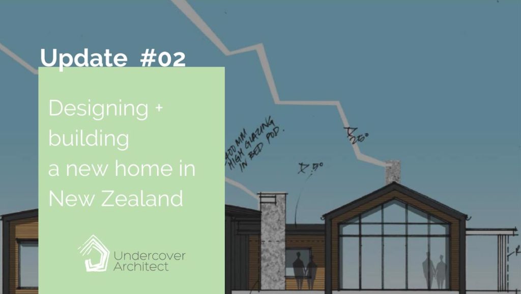
The final design concept drawings are done and we move onto the next stage!
Read on to see the final design concept drawing package, and for the latest update in the New Zealand New Home Project Diary.
In our last instalment, the Anderson’s had decided on a preferred option, and I’d prepared some drawings for feedback.
Now we dive into creating the final design concept drawing package, so they can proceed locally with documentation and approvals.
NB: Not all architects will work like this with their clients. I don’t provide documentation services, so when I work with clients now, I only provide design concepts. They then take them to local designers or draftspeople to then continue the process, have approval and construction drawings prepared and manage it locally. Other designers and architects will provide all of this work for you as one service. It’s important, however you are executing it for your project, that you understand copyright laws and know what’s involved in taking a design to someone else to get drawn up.
So, the purpose of this package of design concept drawings, is to present the design in a way that someone else has sufficient information to convert them into formal documentation.
That means lots of notes, lots of dimensions, and descriptions of windows, ceilings and roof design – both in written and drawing form. Want to know how many drawings you’ll need for your project?
Here is the design concept package for the Anderson’s New Zealand new home …
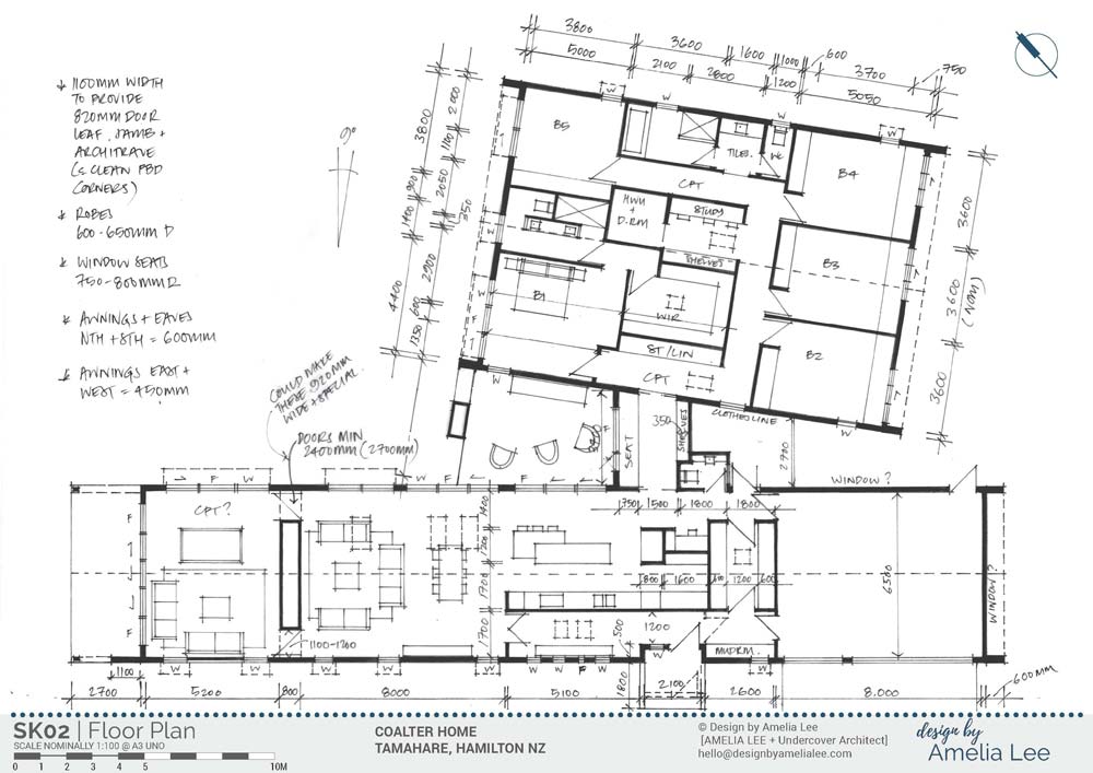
Floor Plan of proposed new home in New Zealand
The proposed floor plan is drawn at 1:100 and shows detail for the home’s overall layout. It also shows internal dimensions for all rooms, layout for the kitchen, and window types and sizes (and how they open). The latter information regarding windows and doors can be correlated with how they’re shown on the elevations as well.
Extra notes provide additional dimensions to be applied as standard across the design. Dashed lines show roofing and window hoods over the top of the floor plan, and proposed skylight locations.
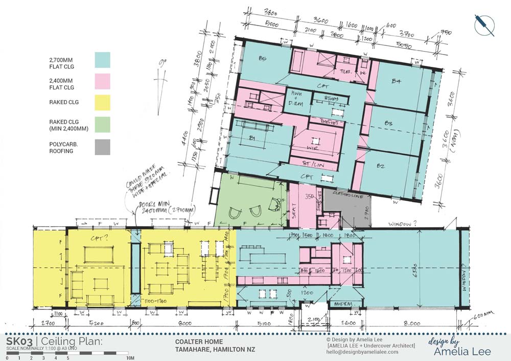
Ceiling Plan of proposed new home in New Zealand
I find that creating these colour coded drawings is a simple way to illustrate how ceilings are to be designed. Anyone drafting these drawings requires this information for the design intent to be carried through properly into documentation.
The aim was to do the bulk of the home in a flat ceiling, so that the roof structure could be constructed in roof trusses, and keep costs down overall. Where the impact would be meaningful, we’ve raked the ceiling (see yellow area). This opens up the volume of the living spaces, and the contrast in volume between those spaces, and the flat ceilings of the adjacent kitchen, will create drama and openness. Those raked ceilings will also have skylights to ensure loads of natural light (especially in winter) enter the main living space of the home.
Remember last instalment when I mentioned the shared storage / fireplace wall between the two living areas, and how we were intending to detail it to maintain a visual connection through? Well, this design proposed one of two options – dependent on budget. One was to do doors either side of the storage wall, with a 2700mm (or 9 feet) flat ceiling over, so that long lines of view could be established when the doors were opened.
The other option (and the one that the Anderson’s are doing … YAY!) is to install glass doors internally in those locations, and run glass over the top of the fireplace / storage wall. That way, the visual line of the raked ceiling runs through both living spaces, as well as loads of light and spaciousness. I can’t wait to see that when it’s finished! It will be incredible.
Lower ceilings (2400mm or 8 feet) are proposed wherever joinery is installed, or in tiled areas, to keep expenses down where possible.
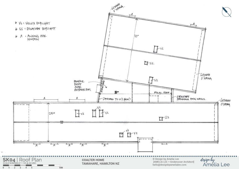
Roof Plan of proposed new home in New Zealand
The roof plan is important for illustrating roof pitches and any plans for gutter locations, and how roofs are intended to sit over the top of each other. The roof is a huge factor in the form of the home, and in a large site like this, it becomes a fifth elevation. So conveying this information accurately is important in maintaining design intent.
I’ve also indicated where skylights are proposed, and the type as well.
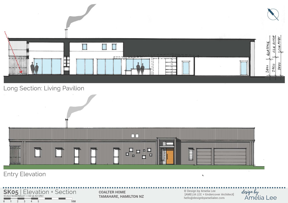
Western Elevation which is the entry elevation of the New Zealand home, and a long section to support information about ceiling and roof design
Elevations are essential for showing the overall form and materiality of the proposed design. They also show window and door information that sometimes isn’t visible on the drawings.
The intention for this home is to wrap the roof and walls in the same cladding, and create a monolithic, simple and elegant gabled form. Almost like an elegant shed (but on steroids!!) This home is not small … it’s intended to house family, and guests, and life, and generations. There’s a balance we need where we don’t want the site to dwarf the home, but we also want the home to have intimacy and elegance about it too. So, the design of the elevation and overall form certainly assists with this.
You’ll see porthole windows in the entry space – these were intended as a bit of fun. I saw the entry space as being a gallery of family photos, with the porthole windows providing framed ‘pictures’ of their own between the family photos.
The entry itself is not over-bearing. It’s sufficiently strong to show where guests need to enter the home, but we didn’t want it to be too significant. It’s designed to protect people from the wind and rain whilst they wait for someone to open the door as well.
The section cuts through the living pavilion, and shows how sliding doors are arranged along the north-eastern façade, and the ceiling steps from being flat (over the kitchen) to raked (over the living spaces).
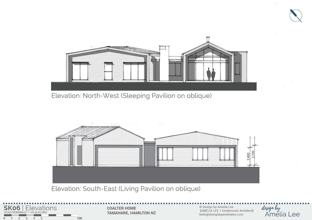
North – west and South – east elevations of the living and sleeping pavilions. The ‘oblique’ view is how we show elevations when the plan is on an angle. So in the top elevation, we’re looking at the living pavilion square-on … and the sleeping pavilion is on the oblique (because it’s at an angle to the living pavilion). The bottom elevation shows the living pavilion on the angle, and we’re looking at the rear of the sleeping pavilion square on.
The ‘end’ elevations of the home work to articulate the two pavilion forms. The northern end of the home is, of course, open to natural light. This elevation hasn’t changed from the previous time I presented it. The Andersons decided they wanted full glazing to the northern end of their living space (not the cedar transom as was an alternative).
The southern end of the home is basically the ‘rear’. However, it is where the kids will have their bedrooms, and so natural light is important. This site is also big enough that the home can easily be circumnavigated, so this elevation will be visible. The ‘wall blades’ use on the northern elevation are brought in here, however we have an eave protrusion that is flat, not gabled – which means that the roof structure can be trussed, and we don’t require additional window hoods over the bedroom windows.
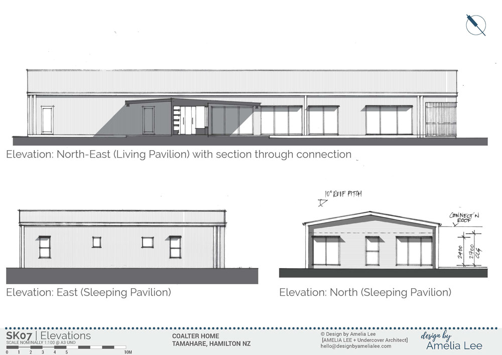
Additional elevations to describe the home
These elevations pick up the remaining facades that aren’t described elsewhere in the package. Here also, the northern elevation of the sleeping pavilion is shown square on – rather than oblique – to help with measuring and scaling for window sizes.
The north-east elevation gives the opportunity to describe how the connection zone will work. This is important, as the roof over the connection zone is low so it tucks under the pavilion roofs – but it can’t be too low overall!
Exciting times ahead …
Now we have the design bedded down, and this package describes it so a draftsperson can convert these drawings into an approval package and construction drawings, it’s time to move on to the exciting stuff.
In the next instalment, I’ll share how the Andersons kicked off construction prior to having their formal approval – as there was specific work they were able to commence without approval. There’s some great photos and footage to share.
Until next time …
 With over 30 years industry experience, Amelia Lee founded Undercover Architect in 2014 as an award-winning online resource to help and teach you how to get it right when designing, building or renovating your home. You are the key to unlocking what’s possible for your home. Undercover Architect is your secret ally
We have just purchased an acre block – north east facing at the rear and overlooking a beautiful river.
We have sketched many plans including one very similar to this! It’s one of my favourites however I wasn’t sure about how the roofline would work. Seeing this plan, which is very similar to our sketch, gives me hope that it could work for us!
What would the approximate budget have been for this house?
Hi Kathy
Thanks for your comment, and I’m glad you found this helpful. I can’t share the budget, and it will vary based on materials, land type, location etc. I would recommend getting a builder involved early in your project to test your budget as your design develops.
– Amelia, UA
Definitely will do that! I’m enrolled in ‘Mange your Build’ and finding it very helpful – thank you!